
Heights
Heights are usually shown on maps by contour lines or spot heights and they give the height above Mean Sea Level (MSL). MSL can vary slightly with time and from place to place, so in Australia a Mean Sea Level value measured in 1966-1968 at 30 tide gauges around the country is used as the reference for height measurement. It is known as the Australian Height Datum (AHD).
There are several methods of measuring the height of a point above MSL/AHD. The choice depends on the accuracy required and the equipment available.
Heights from Barometric Pressure
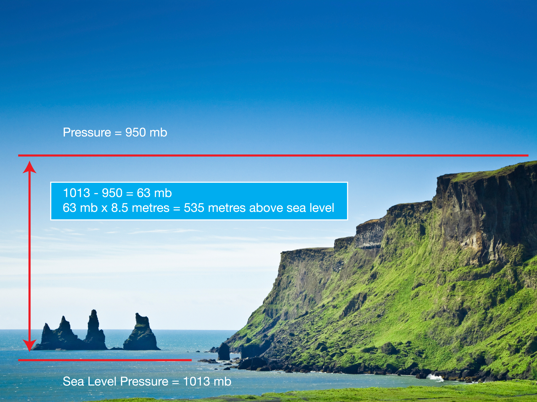
In the past when a direct connection to Mean Sea Level was not possible, the relationship between barometric pressure and height was used to calculate heights above sea level. This is a complex process if the best possible result is wanted, but it is the same principle used in an aircraft’s altimeter.
The pressure at sea level is about 1013 millibars (mb) and it decreases by about 10 mb for every 85 metres of increased height (although this changes as you go higher).
This is not the most accurate method of obtaining heights, but it is relatively simple and can be improved by using several barometers simultaneously on points of known height. Allowance can then be made for changing weather patterns, but even at its best Barometric heighting will result in a height with an uncertainty of about 10 metres.
Heights from Vertical Angles
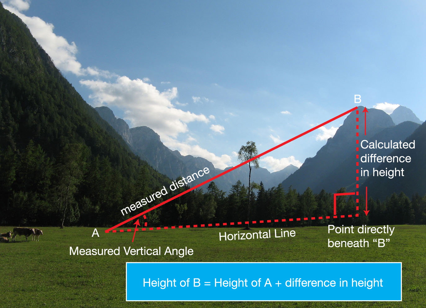
With Triangulation and Traversing, horizontal angles are measured with the theodolite and it is not much more effort to also measure the vertical angles between survey points. Again using trigonometry, the difference in height can be calculated from the vertical angles and the distances. This is called Trigonometric Heighting.
When the distance between the observed points is more than about a kilometre, corrections are also made for the curvature of the Earth and the refraction of the line of sight as it passes through the different atmospheric layers. To cancel out much of the uncertainty due to refraction, vertical angles may be observed simultaneously from each end of the line.
With care and applying all the necessary corrections, a difference in height with an uncertainty of a few decimetres may be obtained over lines up to 30 or more kilometres (a decimetre is one tenth of a meter).
Starting from a point of known height, the simple addition of the calculated differences in height gives the height of each point above MSL.
Heights from Optical Levelling
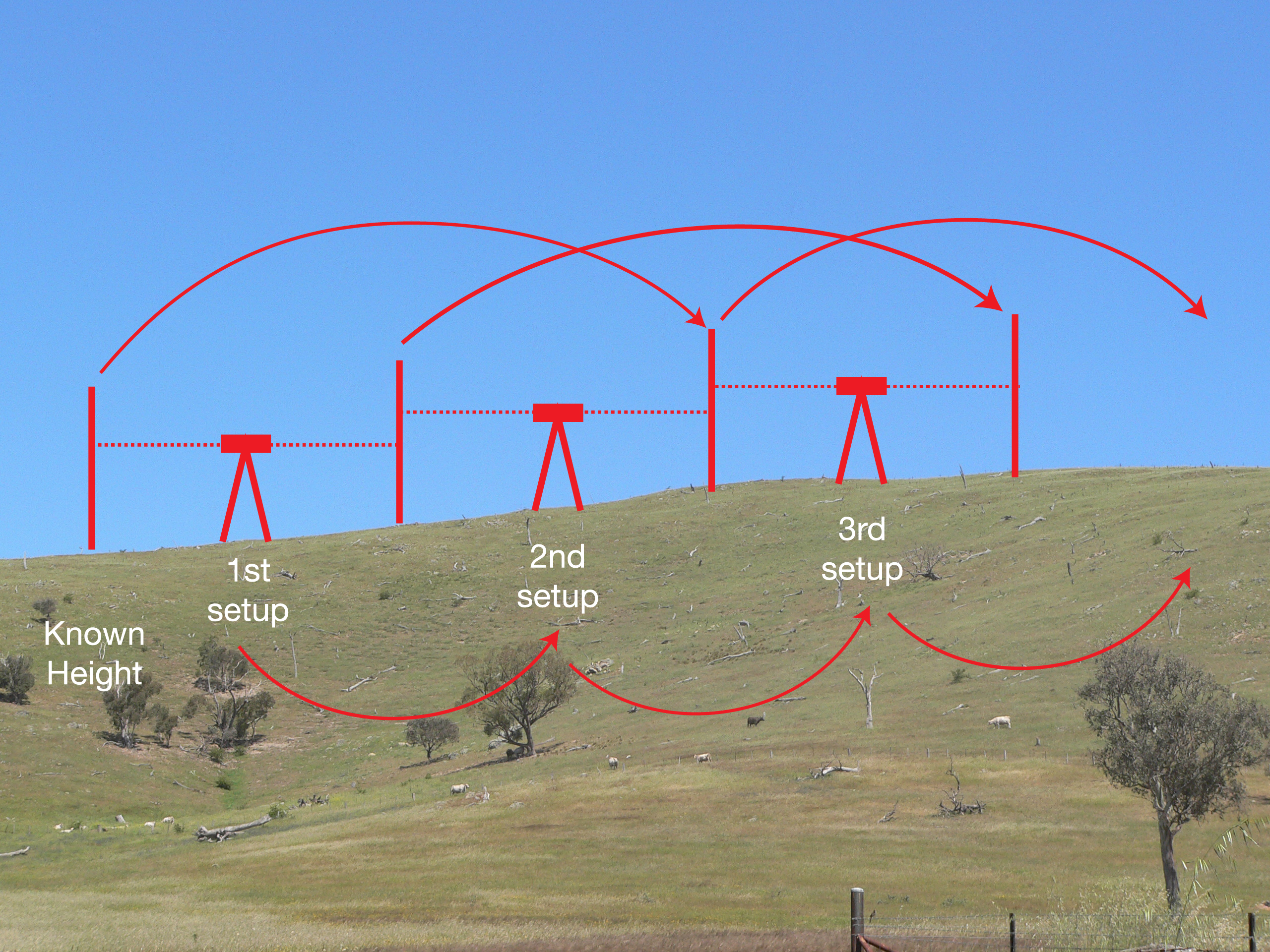
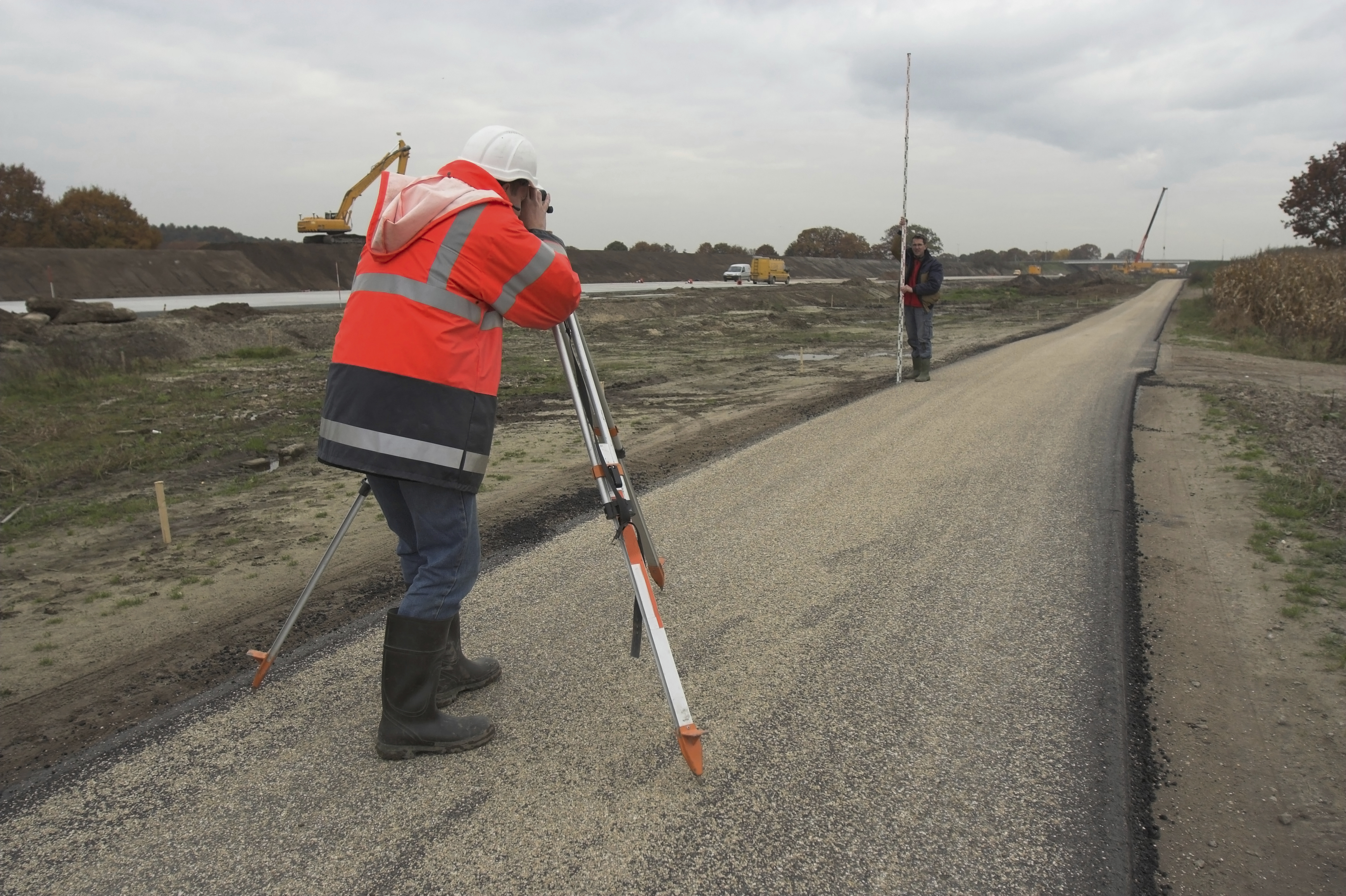
Just as a builder uses a spirit level to make sure a construction is ‘level’, a surveying instrument known as an optical level is used to project a horizontal line in two directions (forwards and backwards) so that differences in height can be measured. At each end of the line being measured the value is noted where this horizontal line intersects a vertical staff (basically just a big ruler). The difference between the values at each end of the line gives the difference in height.
Provided the line of sight is kept relatively short (usually less than 50 metres) the problems of refraction and Earth curvature experienced with Trigonometric Heighting are eliminated. By repeating this process in a leap-frog manner and adding up all the differences in height, the total difference in height between two very distant points can be calculated. If the first point is a tide gauge where Mean Sea Level has been measured, all the points will have known heights above Mean Sea Level.
Over long distances this is a tedious technique, but it produces accurate results. It depends on the instrument used and the care taken, but for the typical standard of optical levelling the accuracy is; 8mm √ (distance in kilometres) which is about 25mm over 10km, or 80mm over 100km.
Over many years, this method has been used to establish more than 100,000 permanent marks (Bench Marks) across Australia. This network of Bench Marks is known as the Australian National Levelling Network (ANLN). Many Government and other organisations have used these Bench Marks as the starting point for their own height surveys and established many more Bench Marks.
These Bench Marks have a measured height above MSL/AHD, but generally no known Latitude and Longitude. They are usually found along the side of roads, where optical levelling is easiest.
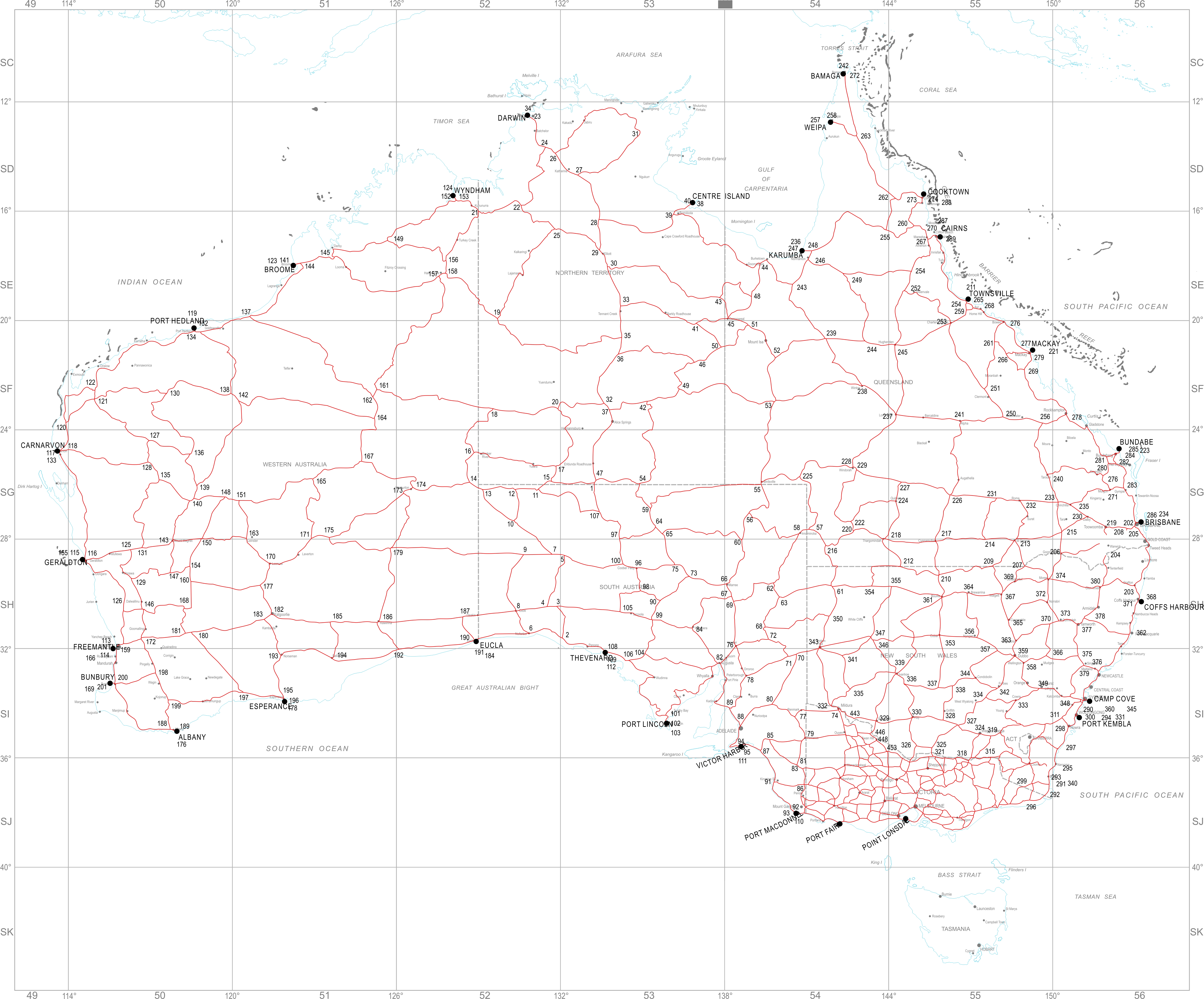
Map of The Australian National Levelling Network (ANLN) (click image to enlarge)
(Note: Tasmania also has a complete levelling network that is not shown in this diagram.)
Explaining Some Jargon – Levelling Instruments
Optical levelling instruments vary greatly, depending on the accuracy needed. Basic instruments are effectively just a telescope mounted on a tripod with an attached bubble to ensure the telescope is horizontal. More sophisticated models use a ‘collimator’ to automatically give a horizontal line, once the telescope is approximately levelled. Many modern instruments use a laser to provide the horizontal line.